
Table of contents
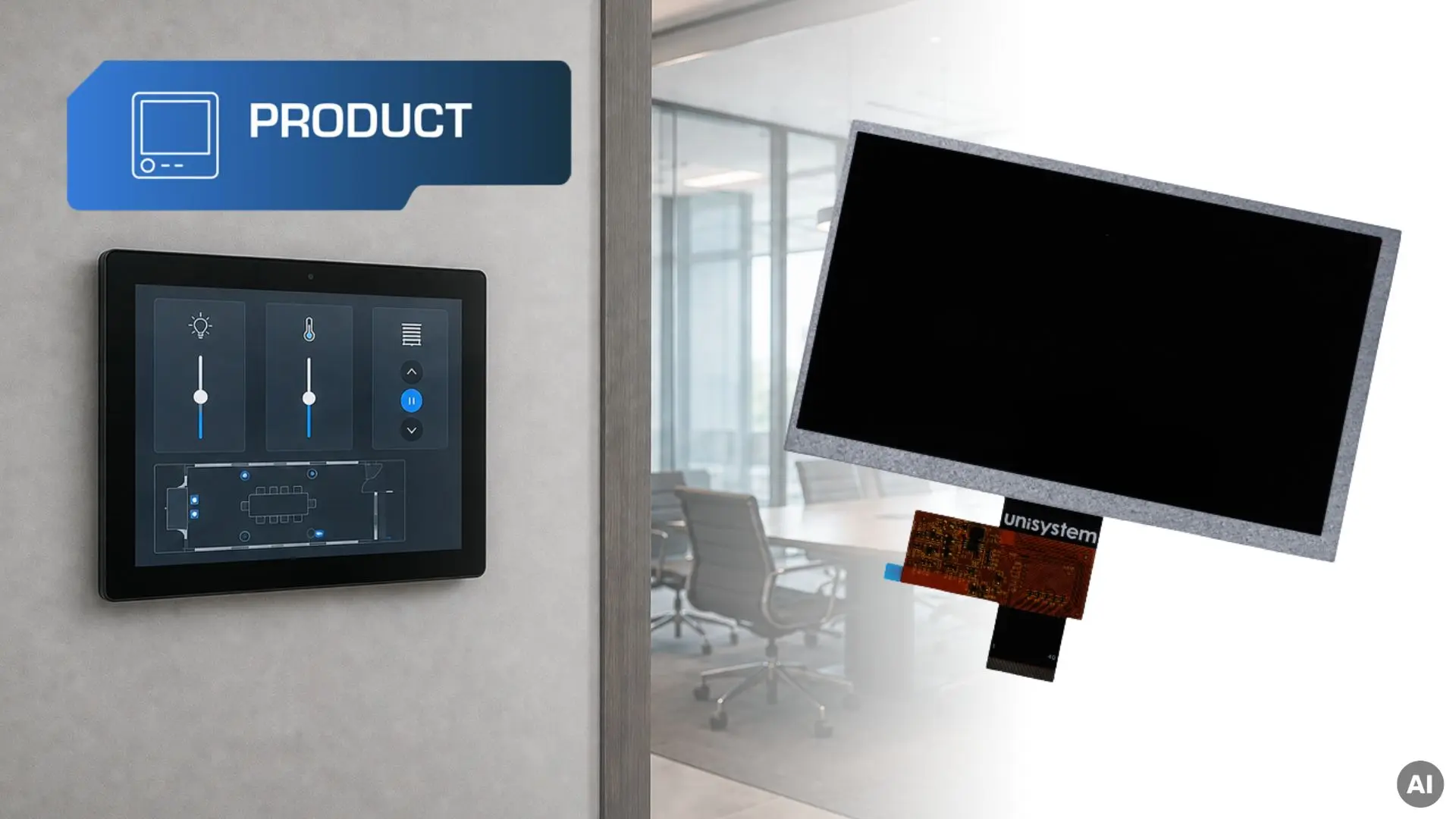
Unisystem Core is a line of LCD-TFT modules developed for typical industrial applications in which the display must maintain stable parameters during intensive, and often continuous, operation. It is an industrial “default” – a solution for projects that require reliability, predictable performance and components suited to professional operating conditions. In this article, we present the concept behind the Core line, its key features and the criteria worth considering when selecting the right variant.
The Unisystem LCD-TFT portfolio includes three product lines designed for different application requirements:
- Unisystem Lite – modules for devices operating indoors under stable conditions,
- Unisystem Core – the industrial standard for intensive use,
- Unisystem Pro – modules for devices operating outdoors, including demanding environments.
The division into Lite, Core and Pro makes it possible to match the module parameters to the actual project requirements – without unnecessarily increasing specifications and solution cost, while avoiding compromises where an application requires higher technical parameters.
Want to learn more about the development of Unisystem’s own-product portfolio? Read the interview: New products developed by Unisystem: industrial LCD-TFTs in three variants.
Origins of Unisystem’s own products: LCD-TFTs
Nearly 30 years of experience in information display technologies have allowed us to understand both the capabilities and limitations of different display technologies, including LCD, OLED and EPD. While working on projects for electronic device manufacturers, we developed solutions tailored to specific applications, operating methods and environmental conditions.
Creating our own LCD-TFT lines is the result of this experience and of addressing challenges that repeatedly arise in industrial projects. We considered not only image parameters, but also module mounting, enclosure design, touch panel integration, control electronics requirements, the way the device is operated and the conditions in which it will be used. Across many projects, the same needs emerged – easier integration, predictable parameters, stable product availability and the flexibility to further adapt the module to a specific design. In industrial applications, resistance to intensive use, stability during continuous operation and a long expected component lifetime are equally important.
The development of Unisystem’s own products is not limited to displays. It also includes complementary solutions that can become part of a complete user interface. One example is the capacitive touch button (UCB045-RGB-CMFDV1), developed for applications in which conventional mechanical components may be insufficient.

The Unisystem Core line was developed for projects requiring industrial-grade parameters, stable operation and components designed for intensive use. It is intended primarily for indoor devices, including applications exposed to stronger ambient lighting, higher operating loads, electromagnetic interference and frequent or continuous operation.
Unisystem Core can therefore be treated as an industrial standard – a starting point for projects in which the display is an important part of the user interface.
Unisystem Core – dozens of LCD-TFT module variants
The Unisystem Core line includes dozens of module variants differing in diagonal size, resolution, interface, touch panel availability and cover glass design. This makes it possible to select a configuration suited to the electronics architecture, mechanical design, interface appearance and intended method of operation.
The key features of each module are encoded in its product designation – the part number (PN). We explain how part numbers are created for Unisystem’s Lite, Core and Pro products in the guide: How to Read Unisystem Part Numbers: A Guide to the Lite, Core, and Pro Lines.
Below, we discuss selected features of the Unisystem Core displays.
Industrial-grade components
One of the distinguishing features of the Unisystem Core line is the use of industrial-grade components. This applies to elements that directly affect image quality, operating stability and module durability – including the LCD-TFT panel, control ICs, backlight system and components responsible for power supply and signal transmission. Their selection takes into account intensive use and frequent or continuous device operation. In industrial applications, what matters is not only the display performance at start-up, but also its repeatability after many thousands of operating hours.
Properly selected components support consistent image quality, predictable performance and a long product lifecycle. This is particularly important in projects where a display failure may disrupt a process, limit access to key information, force a device or an entire installation to stop and, consequently, generate operational losses, service costs and a risk of missed deadlines.
Sizes and resolutions
Unisystem Core modules are available in four popular sizes and corresponding resolutions:
- 7.0” – 1024 × 600 px (WSVGA),
- 10.1” – 1280 × 800 px (WXGA),
- 12.1” – 1280 × 800 px (WXGA),
- 15.6” – 1920 × 1080 px (Full HD).
Brightness matched to industrial applications
The brightness of panels in the Unisystem Core line is 750 cd/m² (600 cd/m² in touch panel variants), providing appropriate image readability in many industrial indoor applications.
Brightness should always be selected according to the actual operating conditions of the device. This is why the Lite, Core and Pro lines use different brightness levels suited to varying ambient light conditions:
- Unisystem Lite – for indoor devices operating under moderate ambient lighting, e.g. in homes, offices, hotels, reception areas, service points and technical facilities,
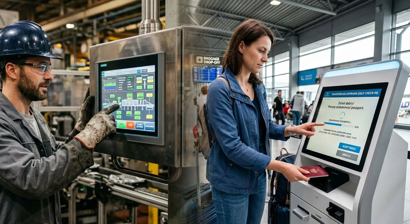
- Unisystem Core – for indoor devices used in more intense lighting, including production halls, logistics centres, shopping malls, hospitals and clinics, railway stations, airports and other public facilities,
- Unisystem Pro – for devices operating outdoors, including in direct sunlight, e.g. at bus stops, platforms, car parks, petrol stations, sports facilities and urban spaces.
Proper brightness selection matters not only for image readability. It can also reduce power consumption and heat generation, while lowering the risk of accelerated backlight wear and excessive panel heating.
Variants with a touch panel
In addition to “open” LCD-TFT modules, the Unisystem Core line also includes variants with a PCAP projected capacitive touch panel. It enables direct on-screen interaction with the interface – without the need for multiple external buttons, switches or knobs.
Touch input in Unisystem Core modules is handled by the ILITEK ILI2520 controller, which allows the touch panel to be configured for the specific device design and operating conditions. Proper configuration and calibration make it possible to adjust sensitivity to factors such as cover glass thickness, intended method of operation, interference levels and contamination on the panel surface. Appropriate tuning may also enable operation with selected types of gloves, including latex or nitrile gloves. These parameters should be set individually – excessive sensitivity can lead to unintended input, commonly referred to as ghost touch.
Depending on the model, variants with a touch panel offer brightness levels ranging from 650 to 900 cd/m². The lower brightness compared with the bare LCD-TFT panel results from the additional optical layers the backlight must pass through. Even so, this range provides good image readability in many industrial applications, including environments with higher ambient light levels.
RGB, MIPI DSI and LVDS interfaces
Depending on the diagonal size and variant, Unisystem Core modules use an RGB, MIPI DSI or LVDS interface. All three are available in selected 7.0” models, while the 10.1”, 12.1” and 15.6” modules use LVDS. This variety of interfaces makes it possible to match the display to the electronics architecture, connection design and requirements relating to bandwidth and transmission immunity to interference.
RGB
RGB is a parallel interface in which data for individual colour components and synchronisation signals are transmitted over separate lines. It is supported by many microcontrollers and processors equipped with an LCD controller, enabling direct integration of the LCD-TFT with the device electronics.
Because of the large number of signal lines, the interface requires careful connection design and PCB routing. It is used primarily in applications where the distance between the display and the control unit is short and the number of required connections is not a major constraint.
MIPI
MIPI DSI is a high-speed serial interface developed for transmitting image data to displays. It uses a small number of signal lines, helping to reduce the number of connections and allowing efficient placement of components on the PCB.
The interface is used mainly in compact designs where the display is located close to the processor. Its use requires a control unit equipped with a MIPI DSI controller.
LVDS
LVDS transmits the image signal using differential wire pairs. This transmission method helps maintain signal integrity and reduce susceptibility to electromagnetic interference.
The interface enables stable transmission of large amounts of data, which is why it is commonly used in higher-resolution LCD-TFTs and in designs requiring a longer connection between the module and the image-generating electronics.
USB-C and HDMI – further development of Unisystem’s own products
As part of the continued development of our own-product portfolio, we plan to introduce LCD-TFT variants with an additional PCB supporting both USB-C and HDMI. In this configuration, either interface can be used for video transmission, simplifying integration with industrial computers, single-board computers and other devices that provide a ready-to-use video signal.
The solution is plug & play – it allows the module to be connected to a compatible video source without the need to directly support the panel’s native interface. This simplifies display bring-up and reduces the amount of work required on the control electronics side.
USB-C
USB-C is a universal connector that – depending on the implementation – can support video, data, touch panel signals and power delivery. It can reduce the number of separate cables and connectors, which may simplify assembly and display integration with the device. The available functionality depends on the capabilities of the control unit and the module electronics. A USB-C connector alone does not automatically mean that video transmission or power delivery is supported.
HDMI
HDMI is a digital interface for transmitting ready-to-use video and audio signals. It is widely used in devices equipped with a standard video output and can simplify display integration with the control unit, as the processor does not need to support the panel interface directly. The display module must, however, include additional electronics to receive and process the HDMI signal.
RGB vs. MIPI vs. LVDS vs. USB-C vs. HDMI
The table below presents the key characteristics of RGB, MIPI DSI, LVDS, USB-C and HDMI from the perspective of integrating an LCD-TFT with the device electronics. The comparison is indicative – actual transmission capabilities depend, among other things, on the display resolution and refresh rate, PCB design, connection length and quality, control unit parameters and the implementation of the interface.
| Feature | RGB | MIPI DSI | LVDS | USB-C | HDMI |
| Type of solution | Direct panel interface | Direct panel interface | Direct panel interface | Connector supporting various transmission standards | Digital video and audio interface |
| Video transmission method | Parallel | Differential | Differential | Depends on the implemented standard | Serial, digital |
| Availability in the Core line | Selected 7.0” variants | Selected 7.0” variants | 7.0”, 10.1”, 12.1” and 15.6” variants | Planned solution | Planned solution |
| Number of connections | 24 data lines – 8 each for R, G and B – plus VSync, HSync and DCLK lines | Usually 4 differential pairs, e.g., 8 signal lines; some configurations may use fewer pairs | Usually 4 differential pairs, e.g., 8 signal lines | One compact connector | One signal connector |
| Typical connection length | Short connections on the PCB or between closely located components | Short connection between the processor and the display | Suitable for longer connections as well | Depends on the standard and cable used | Suitable for connections using an external cable |
| Immunity to interference | Low: parallel, single-ended lines are susceptible to interference, crosstalk and increased electromagnetic emissions | High bandwidth, suited to compact modules carrying larger amounts of data | High bandwidth, suitable for higher-resolution modules | Depends on implementation and cable quality | Low susceptibility when an appropriate cable is used |
| Bandwidth and resolution | Suitable mainly for lower and medium resolutions | High bandwidth with a small number of lines | High bandwidth, suitable for higher resolutions | Depends on the video transmission standard used | Depends on the HDMI version and module electronics |
| Control unit requirements | LCD controller supporting RGB | MIPI DSI controller | LVDS transmitter or suitable converter | Support for a compatible USB-C transmission mode | HDMI output |
| Power delivery capability | No | No | No | Yes – depending on the implementation | No |
| Touch transmission through the same connector | No | No | No | Yes – depending on the module design | No |
| Impact on PCB design | Requires routing many parallel lines and maintaining timing relationships | Requires correct routing of high-speed differential pairs | Requires controlled routing and matching of differential pairs | Can reduce the number of connectors, but requires additional control ICs | Simplifies connection to a computer, but increases the amount of electronics in the module |
| Typical use | Designs with the display located close to the control unit | Compact devices with a direct display-to-processor connection | Designs requiring stable transmission, higher resolution or a longer connection | Devices requiring simplified cabling and integration of multiple functions in one connector | Devices operating with computers and units equipped with a standard video output |
RGB, MIPI DSI and LVDS are interfaces used for direct control of an LCD-TFT panel. USB-C and HDMI represent a different integration model – they require additional electronics on the module side, but can simplify connection to a ready-made computing platform.
The final interface choice should take into account the capabilities of the control unit, display resolution, connection length and design, available space for electronics, as well as bandwidth requirements, transmission immunity to interference and the way the module will be integrated into the device.
Cover glass
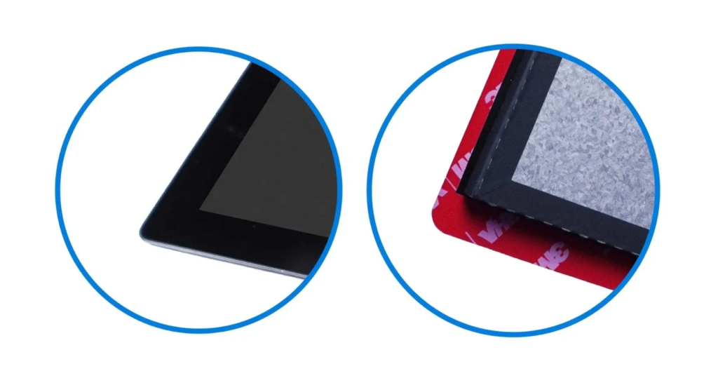
In Unisystem Core modules with a touch panel, cover glass is a standard part of the design. It protects the display and touch panel against scratches, pressure and other mechanical damage, while its design can be adapted to the mounting method and front panel design of the device. The cover glass is available in two variants: without mounting tape and with mounting tape.
Cover glass without mounting tape
In this variant, the cover glass does not have factory-applied mounting tape, providing greater flexibility when developing a custom method for mounting the module in the enclosure or front panel. It has a rectangular shape, allowing it to be adapted to the individual mechanical design.
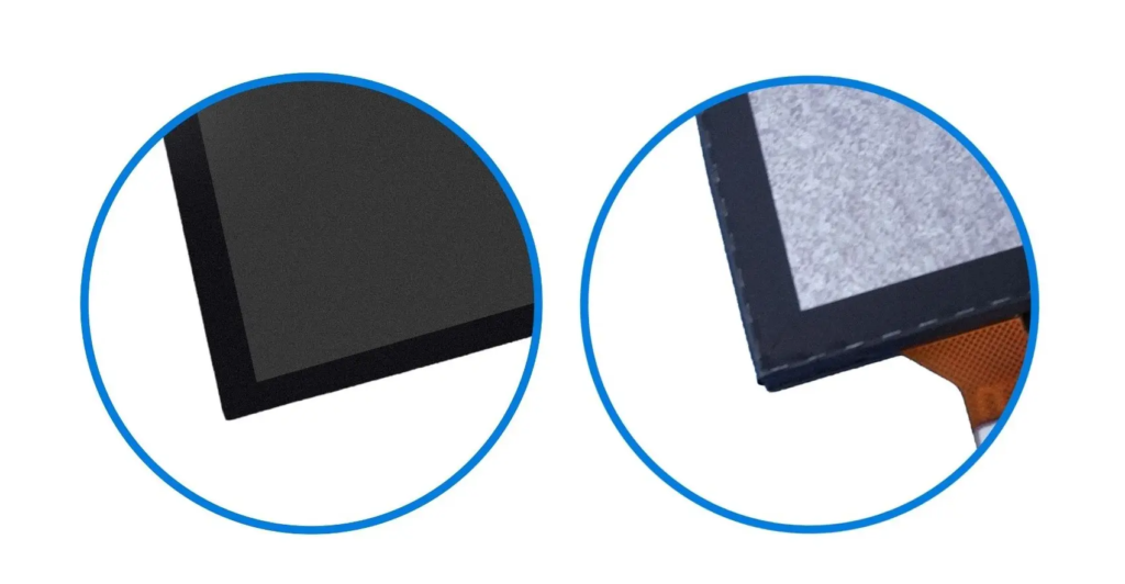
Cover glass with mounting tape
In this variant, the glass is equipped with tape that makes it easier to position and mount the module in the enclosure or front panel. This solution can streamline assembly and improve repeatability in serial production. The glass also has rounded corners, giving the front of the device a softer finish.
Optical bonding as standard
All LCD-TFTs from the Unisystem Lite, Core and Pro lines that are equipped with a touch panel use optical bonding as standard. The process involves bonding the display, touch panel and cover glass over their entire surface using a transparent optical material. Removing the air gap between the individual components reduces internal light reflections, improves image contrast and increases the mechanical rigidity of the entire module. This is particularly important in industrial applications where the display must not only provide suitable readability, but also maintain durability during intensive operation and exposure to shocks, vibration and localised mechanical loads.
MTBF = 100,000 hours
MTBF (Mean Time Between Failures) is a statistical indicator describing the average expected operating time between failures in an analysed population of devices. It does not represent the guaranteed operating life of an individual module, but it can be used to compare the expected reliability of solutions designed for similar operating conditions.
For Unisystem Core modules, the declared MTBF is 100,000 hours. The line has therefore been developed for long-term operation, including devices running continuously. Actual module lifetime also depends on operating conditions, temperature, power supply, backlight intensity and the thermal design of the complete device.
What applications are Unisystem Core modules designed for?
Unisystem Core is intended primarily for industrial devices operating indoors, including applications involving intensive use, strong ambient lighting or an increased risk of electromagnetic interference. The line can be used, among others, in:
- HMI, operator, control and monitoring panels,
- machine and production line control systems, including panels used to configure operating parameters,
- measurement, diagnostic and control equipment,
- self-service terminals used, among other things, for placing orders, registering appointments, making payments or handling requests,
- information kiosks and totems,
- user flow registration and management systems, including queue management systems, ticket dispensers, check-in terminals and entry registration systems,
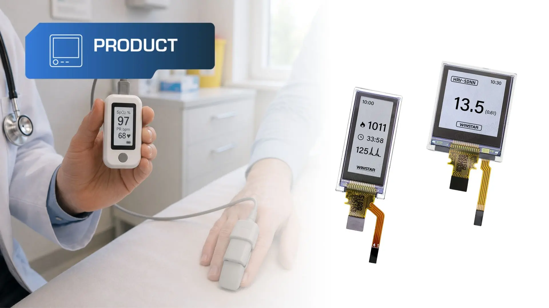
- medical and laboratory equipment, such as analysers, diagnostic equipment, incubators and parameter monitoring devices,
- infrastructure monitoring systems,
- solutions used in warehouses and logistics centres – workstation terminals, order-picking systems and panels for managing the flow of goods.
Unisystem Core is a line designed for industrial indoor devices where predictable operation, reliability and long-term use are key requirements. These solutions are not intended for direct exposure to weather conditions. If the device is to operate outdoors, in direct sunlight or under increased mechanical loads, the Unisystem Pro line should be considered.
The choice of the right model should primarily be based on the actual application requirements and the conditions in which the device will be used.
Looking for a solution tailored to your project?
Contact us and tell us about your project requirements. Together, we will select the right display variant or define the scope of customisation needed to meet the application requirements.