
Article summary generated by AI — it may contain errors.
Table of contents
A part number, or PN for short, is a unique product identifier that describes its key technical features. This type of designation is widely used by electronic component manufacturers. Unisystem also uses its own product coding system. In this article, we explain how to read the part numbers of LCD-TFTs in the Unisystem Lite, Core, and Pro lines.
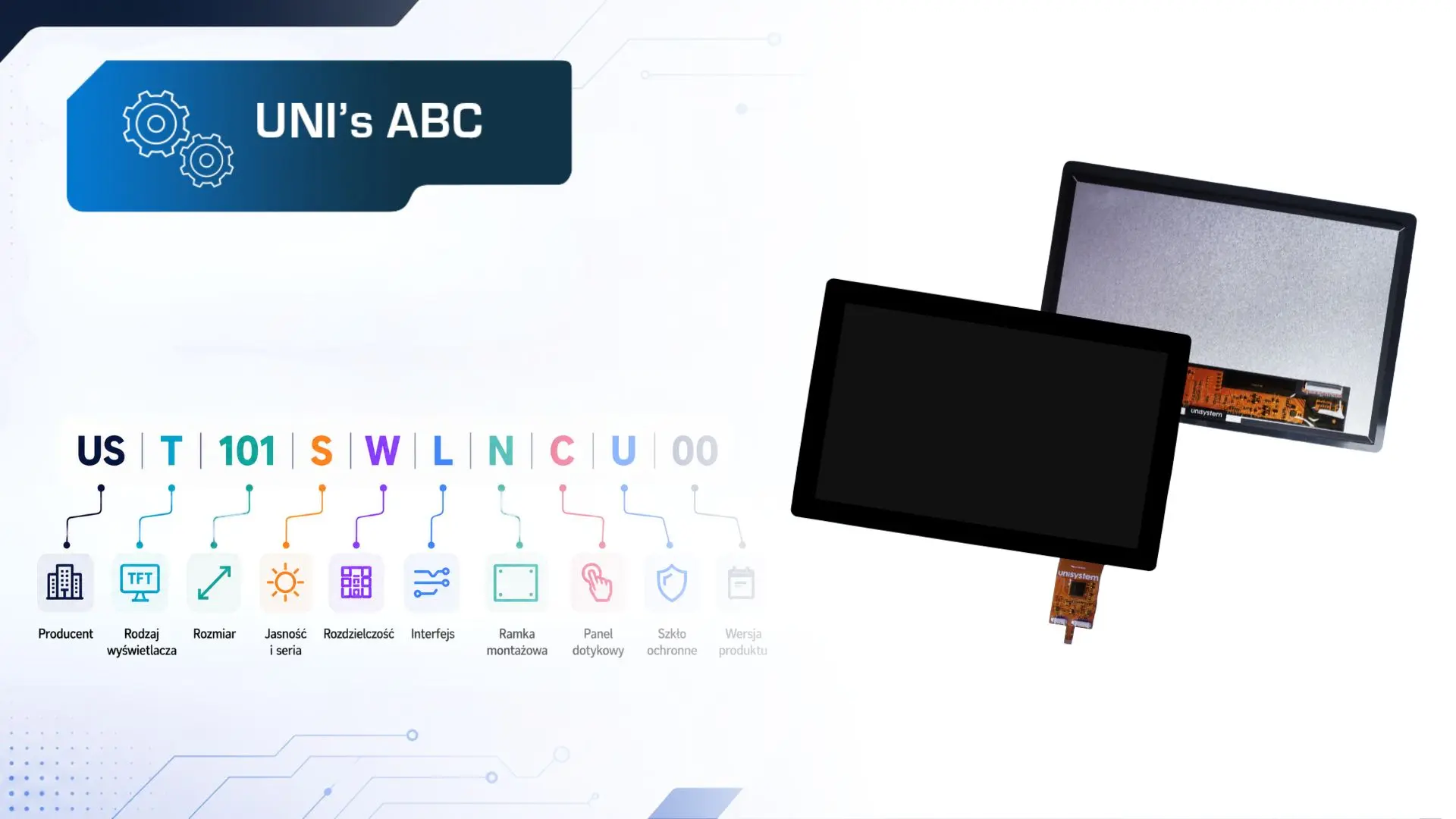
At first glance, a part number may look like a random string of letters and digits. In fact, each element has a specific meaning. The individual characters provide information about features such as the manufacturer, technology, size, brightness, resolution, interface, additional components (including a touch panel), and the product version.
Importantly, changing even a single letter or digit may indicate a different module. Correctly interpreting the part number is therefore essential when selecting an LCD-TFT for a particular application, placing an order, comparing variants, or planning future versions of a device.
UST101SWLNCU00 by Unisystem
We will use UST101SWLNCU00 as an example.
This is a 10.1-inch LCD-TFT by Unisystem, representing the Core line. The portfolio also includes two other product lines – Lite and Pro. They differ primarily in their intended applications and operating requirements, including brightness and resistance to environmental conditions. You can find more information in our article: New Unisystem LCD-TFT Lines: Lite, Core and Pro.
Let’s break this part number down:
US | T | 101 | S | W | L | N | C | U | 00
Each element represents a specific product feature, as explained below.
Manufacturer (US)
The first letters of a part number often identify the manufacturer or brand associated with the product. This makes it possible to determine which portfolio a particular module belongs to from the very beginning of the code.
Unisystem products use the designation US, indicating that the module is part of Unisystem’s own product portfolio.
Display Type (T)
The next character identifies the display type.
For the LCD-TFT product lines discussed here, the designation “T” indicates TFT technology.
TFT, or Thin-Film Transistor, is an active-matrix LCD technology. Each pixel is controlled by a separate transistor, providing good image quality, consistent colour reproduction, good contrast, and fast response times.
Display Size (101)
The next three digits in the part number indicate the display’s diagonal size in inches.
Unisystem’s product portfolio includes popular diagonal sizes commonly selected for industrial projects.
Available variants include:
- 050 – 5.0 inches,
- 070 – 7.0 inches,
- 101 – 10.1 inches,
- 121 – 12.1 inches,
- 156 – 15.6 inches.
The model discussed here is designated 101, indicating a diagonal size of 10.1 inches.
Brightness and Product Line (S)
The next letter in the part number indicates the panel brightness level, indirectly linking the product to one of the three Unisystem lines: Lite, Core, or Pro. Brightness is one of the key parameters that differentiates these lines and indicates their intended applications.
Three designations are used:
- L – low brightness – Lite line: 600 cd/m² without a touch panel and 500 cd/m² with a touch panel,
- S – standard brightness – Core line: 750 cd/m² without a touch panel and 600 cd/m² with a touch panel,
- H – high brightness – Pro line: 2,000 cd/m² without a touch panel and 1,700 cd/m² with a touch panel.
The model discussed here uses the designation S, meaning standard brightness. This indicates that the product belongs to the Core line.
Resolution (W)
The next letter in the part number indicates the display resolution.
The following designations are used for Unisystem products:
- M – 800 × 480 px, WVGA,
- S – 1024 × 600 px, WSVGA,
- W – 1280 × 800 px, WXGA,
- X – 1024 × 768 px, XGA,
- F – 1920 × 1080 px, FHD.
The model discussed here uses the designation W, indicating a resolution of 1280 × 800 px (WXGA).
WXGA is well-suited to interfaces that present more information than basic messages or simple numerical values. It provides sufficient space for controls, status information, charts, alarms, parameter lists, and more complex application screens. On a 10.1-inch screen, this resolution ensures good image readability and sufficient screen space for applications such as HMI panels.
Interface (L)
The next letter in the part number indicates the display’s signal interface.
The following designations are used:
- L – LVDS,
- M – MIPI,
- R – RGB,
- D – eDP,
- H – HDMI.
The model discussed here uses the designation L, indicating an LVDS interface.
Different interfaces may be used depending on the model and diagonal size. The widest selection is available for 7.0-inch models, which may feature LVDS, MIPI, or RGB. This is due to the typical architecture of these panels and the different ways in which they can be integrated with control electronics. In 7.0-inch models, RGB is suitable for simpler applications, MIPI for compact devices with limited space for electronics, and LVDS for projects requiring stable image signal transmission and greater resistance to interference.
Larger models – 10.1, 12.1, and 15.6 inches – primarily use LVDS. These modules generally operate at higher resolutions and therefore require stable transmission of larger amounts of data between the controller and the panel. Compared with RGB, LVDS requires fewer signal lines, provides greater resistance to interference, and simplifies signal routing in industrial applications.
Further development of plug-and-play solutions is also planned, which is why interfaces such as HDMI have already been included in the coding system.
Mounting Frame (N)
The next character indicates whether the module is equipped with a metal mounting frame.
Two variants are available:
- F – with a metal mounting frame,
- N – without a metal mounting frame.
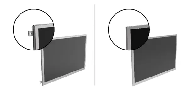
A metal mounting frame is a structural component that facilitates the mechanical securing of the module within a device and its integration with the enclosure, front panel, or another part of the structure. Depending on the project requirements, it can simplify assembly, increase module rigidity, and improve the repeatability of the production process.
The frameless variant offers greater flexibility in device design. It may suit a dedicated mounting method, a custom enclosure, or a non-standard front panel.
The model discussed here is designated N, indicating a variant without a metal mounting frame.
Touch Panel (C)
The next character in the part number indicates whether the variant includes a touch panel.
The following designations are used:
- N – without a touch panel,
- C – with a capacitive touch panel.
Each product line is available in variants with CTP (projected capacitive touch panel) technology.
The modules use touch controllers selected for the requirements of each product line. The Lite line uses Goodix GT928 controllers, while the Core and Pro lines use the ILITEK ILI2520 controller.
A capacitive touch panel enables intuitive interaction, as is familiar from modern user interfaces. It is well-suited to applications where ease of use, precise touch response, front-panel aesthetics, and integration with protective glass are important. The touch controller supports stable panel operation and enables tuning of touch performance to the device’s operating conditions.
The model discussed here is designated C, indicating that the module is equipped with a capacitive touch panel.
Protective Glass (U)
The penultimate letter indicates the protective glass variant.
Protective glass shields the LCD-TFT and touch panel against mechanical damage, scratches and pressure applied by users. It is particularly important in frequently operated devices, especially those installed in public spaces.
In modules with a touch panel, protective glass is a standard structural component. However, it can be supplied in different variants depending on the application requirements and the design of the device’s front panel.
Part numbers for products in the Lite, Core and Pro lines include three protective glass designations:
- N – without protective glass,
- E – protective glass without mounting tape,
- U – protective glass with mounting tape and rounded corners.
The N variant indicates a module without protective glass. In practice, this is a “bare” LCD-TFT panel without an additional protective glass layer.
The E variant indicates protective glass without mounting tape, joined to the module using optical bonding. This solution provides additional protection for the front of the LCD-TFT, improves image readability and increases the rigidity of the entire module.
The U variant indicates protective glass with mounting tape and rounded corners, joined to the module using optical bonding. It may be selected when the design requires not only display protection but also an aesthetically finished front panel, greater user comfort, softer edge design and easier integration with the device enclosure or front panel.
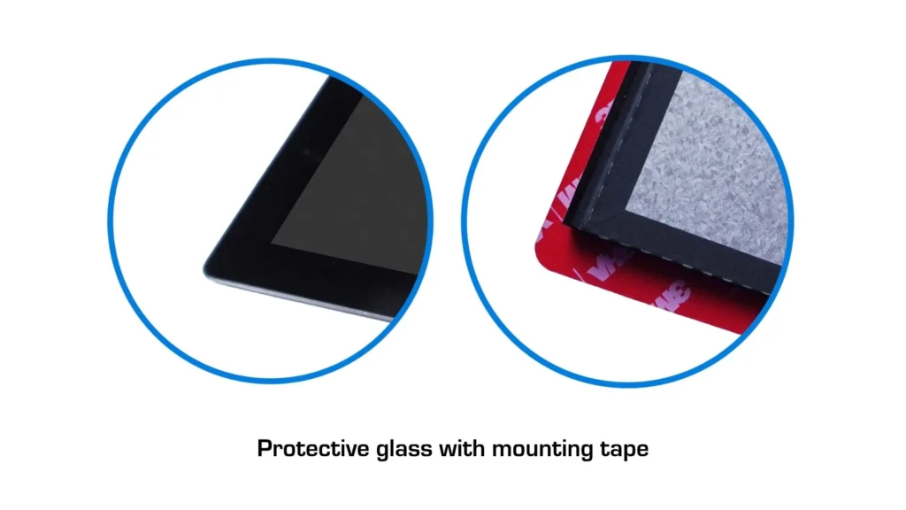
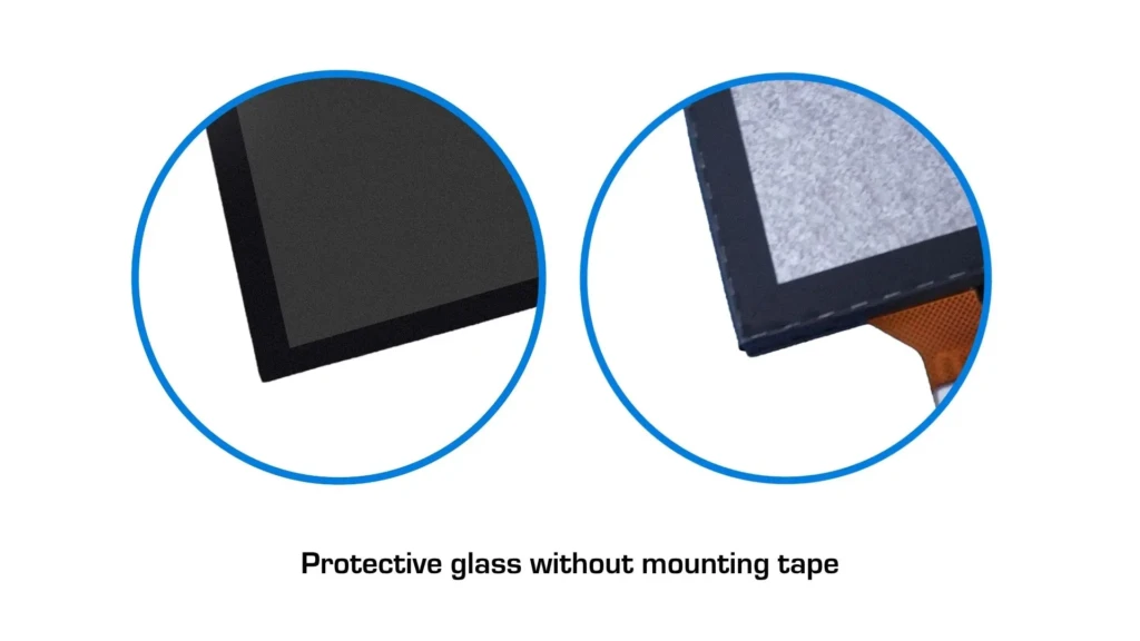
Optical bonding is standard in Unisystem LCD-TFTs. The process involves filling the space between the LCD-TFT, touch panel, and protective glass with a specialised optical material. This reduces light reflections, improves image readability, and increases the mechanical rigidity of the entire module.
The model discussed here is designated U, indicating a variant with rounded protective glass that is optically bonded to the panel and equipped with mounting tape.
Product Version (00)
The final two digits of the part number indicate the product version. The standard designation is 00, which identifies the base version.
If design, technological, or functional changes are introduced to a module, its version number may change. This makes it possible to distinguish between subsequent variants of the same product and identify modules accurately throughout ordering, technical documentation, production, and servicing.
The model discussed here uses the designation 00, indicating the base version.
An example of a modified version is the UST101HWLNCU10, a 10.1-inch LCD-TFT by Unisystem in the Pro line. Its part number ends in 10, indicating a modified module version.
This variant features an additional IR layer – a thermal coating designed to reduce heat build-up in the LCD panel caused by solar radiation. This is particularly important in outdoor applications, where the screen may be exposed to direct sunlight, high temperatures, and dynamically changing environmental conditions.
This is why the final two digits of the part number are important. They do more than organize the product range: they identify a specific module version and indicate potential differences compared with the base variant.
Why Is Reading a Part Number Correctly So Important?
A part number provides a quick way to identify the key features of an LCD-TFT, provided that the manufacturer’s coding system is understood. Correctly interpreting the product number makes it possible to determine:
- which product line the module belongs to,
- its diagonal size,
- its resolution,
- which signal interface it uses,
- whether it is equipped with a touch panel,
- whether it includes protective glass,
- whether it has a mounting frame,
- whether it is the base or a modified version.
This is important because even a small difference in configuration can affect the device’s mechanical design, integration method, image readability, module durability, or compatibility with the control electronics. If you are designing a device with a screen and looking for the right LCD-TFT, contact the Unisystem team. We will assess your application requirements, operating environment, and mechanical and electronic design assumptions, then recommend the product best suited to your project.