Table of contents
In this series of articles, we present the most popular interfaces used to data transfer, in this case – images, between devices providing data such as processors/controllers or computers and devices presenting data such as displays and monitors.
When describing ‘interfaces’, we think of connecting the devices used to data transfer. They are essential to present any content on the visual information carriers, e.g., LCD-TFTs.
We can divide interfaces into two groups:
- internal solutions – in these solutions, we directly connect components of the same device (usually set in the same enclosure) so controller and display; among them, e.g., interfaces to image transfer (RGB, LVDS, eDP, MIPI DSI, and Vx1) as well as interfaces to various data transfer, including image transfer (SPI, I2C, RS232, and 8- or 16-bit parallel solutions);
- external solutions – in these solutions, we connect two separate devices, e.g., computer and monitor via cable; among them, e.g., HDMI, DVI, VGA, or DP.
We can also divide interfaces due to the type of data transmission to parallel interfaces, in which 1-bit information is transmitted via several lines, and serial interfaces, in which subsequent 1-bit information is transmitted via a single line.
In this article, we describe five interfaces: RGB, LVDS, eDP, MIPI DSI, and Vx1.
***
In recent years, the RGB and LVDS interfaces are commonly used in LCD-TFTs. In the handbooks from a few years ago, you can read that choosing between RGB and LVDS interface depends on the resolution of LCD-TFT. For that time, one recommended the RGB interface for resolutions lower than 640×480 px and the LVDS interface for resolutions higher than 800×480 px. However, due to steady technology development, these values have already changed. Currently, we use the RGB interface for resolutions lower than 1280×800 px and the LVDS interface for resolutions higher than 320×240 px. Let’s add that today’s advanced microprocessors and microcontrollers are upgraded with RGB and/or LVDS driver, which simplify implementing LCD-TFTs in end-devices.
RGB (Red, Green, Blue)
The RGB interface is based on parallel data transfer via at least a few wires. Each line is capable of transmitting 1-bit information that determines the intensity of the RGB color of a pixel. Depends on the type of RGB interface, there is a required number of wires, e.g., in 24-bit variants, you need to use 24 wires for each pixel.
In the RGB interfaces, there are five types of signals:
- VSYNC (Vertical Synchronization used to synchronized data for columns of pixels on display);
- HSYNC (Horizontal Synchronization used to synchronized data for rows of pixels on display);
- D0…DXX (with a separate line for each bit of information);
- DCLK (Dot Clock used to synchronize data);
- DE (Data Enable – mode used to confirm data transfer accuracy).
The RGB interface is valued for performance – its bandwidth is estimated even up to 1.2 Gbit/s. However, to achieve such values, you need to use more wires in one configuration, which causes higher emission of electromagnetic interferences.
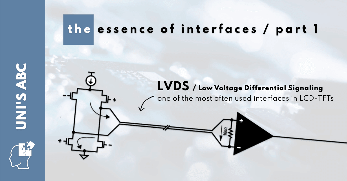
LVDS (Low Voltage Differential Signaling)
The LVDS interface used to image transfer requires four differential pairs – one to clock signal transfer and three to data transfer. It provides simplex and serial communication – each bit of data is transmitted in one direction and in a row. The information is transferred as the difference between the voltages on a pair of wires; then, it is compared at the receiver. In the LVDS interface, there are three modes of data synchronization: VSYNC (Vertical Synchronization), HSYNC (Horizontal Signalization), and DE (Data Enable).
The LVDS interface is also valued for its performance. Usually, it is used in point-to-point topology (with one transmitter and one receiver), which provides bandwidth up to 3.125 Gb/s, even within a few meters distance between devices. What is more, it is relatively resistant to electromagnetic interferences.
On Unisystem’s offer, you can find a wide range of LCD-TFTs, which support LVDS interface – check out the standard and wide-screen solutions.
eDP (embedded DisplayPort)
The eDP interface, created by VESA (Video Electronics Standards Association), has been developed to implement in consumer electronic devices with embedded LCD-TFTs. It seems that it was a success, especially in the computer industry – in this area, we can notice that the eDP interface displace the LVDS interface. However, the eDP interface is not commonly used in microprocessors or microcontrollers.
The eDP technology draws on DP, so Display Port standards, bases on differential pairs of signals – one pair to clock signal transfer and at least one pair to data transfer; beyond them, there are also half duplex AUX channels intended to configure LCD-TFT’s controllers. We can say that the structure of the eDP interface is similar to the structure of the LVDS interface, whereby the transferred information is “packed” in a different way – in the eDP interface, it is a serial transfer of compressed packages of information. In the eDP interface, there are three modes of data synchronization: VSYNC (Vertical Synchronization), HSYNC (Horizontal Signalization), and DE (Data Enable).
The eDP interface is recommended for LCD-TFT up to 3840×2160 px while 60 FPS and 24 bpp. However, the best image quality is gained for 1920×1080 resolution while 240 FPS and 24 bpp or 2650×1600 resolution while 60 FPS and 48 bpp. Its bandwidth can be even up to 1.62 Gb/s. It is also worth noticing that the eDP interface is relatively resistant to electromagnetic interferences.
MIPI DSI – DSI (Display Serial Interface) by MIPI (Mobile Industry Processor Interface) Alliance
The DSI technology has been developed by MIPI Alliance. It has been designed to apply mainly in portables, such as, e.g., smartphones, tablets, and laptops, but it can also be used, e.g., in mobile measuring devices.
The MIPI DSI interface also bases on differential pairs of signals. It provides full duplex communication so in both directions. The information is transferred as compressed packages using two modes of data synchronization:
- Low Power (LP) – in this mode, the clock signal is suppressed; the information about the clock signal is transferred by a pair of wires for data transfer; it is used primarily to transmit information/initialization to displays;
- High Speed (HS) – in this mode, the clock signal is transferred by separate pair of wires; it is used only to transmit images.
The communication protocol consists of two sets of instructions: Display Command Set (DCS) – a set of universal commands defined by DSI standard, such as, e.g., Sleep, Enable, or Invert Display and Manufacturer Command Ser (MCS) – a set of commands defined by the display’s producer; they can concern, e.g., inputting the data to the non-volatile memory of the screen’s driver.
The MIPI DSI’s crucial assets are high efficiency obtained with low power consumption and immunity to electromagnetic interferences.
On Unisystem’s offer, there are some LCD-TFTs with the MIPI DSI interface. Among them, e.g., 4-inch square displays by Winstar, which can be applied in various applications.

Vx1 (V-by-1 / V-by-One)
Along with the market introduction of FHD (1920×1080) and UHD (3840×2160) displays, there came a demand for an interface, which would be even more resistant to electromagnetic interferences than the LVDS interface. There it is – the Vx1 interface developed by Thine Electronics.
The Vx1’s image transfer standard is similar to the LVDS image transfer standard, although Vx1 guarantees the low production cost with the high speed of data transfer. It can be even 840 Mb/s for each differential pair of wires (even at a distance of 10m!). The Vx1 interface is an asynchronous solution – the clock signal is transferred via data wires, so there are no clock signal wires. In effect, the total amount of pairs of wires is reduced. Let’s compare: to boot a screen of Cinema-FHD (2560×1080) resolution with 30-bit color depth and 120 Hz refresh rate, you need to use 24 pairs of wires in the LVDS interface or… 4 pairs of wires in the Vx1 interface.
In the table, we present the number of pairs of wires depending on the display’s resolution, color depth, and refresh rate.
| resolution | color depth | refresh rate (pixel clock) | number of lines |
|---|---|---|---|
| 1280×720 | do 36-bitów | 60 Hz (74.25 MHz) | 1 |
| 1280×720 | do 36-bitów | 120 Hz (148.5 MHz) | 2 |
| 1280×720 | do 36-bitów | 240 Hz (297 MHz) | 4 |
| 1920×1080 | do 36-bitów | 60 Hz (148.5 MHz) | 2 |
| 1920×1080 | do 36-bitów | 120 Hz (297 MHz) | 4 |
| 1920×1080 | do 36-bitów | 240 Hz (594 MHz) | 8 |
| 1920×1080 | do 36-bitów | 480 Hz (1188 MHz) | 16 |
| 2560×1080 | do 36-bitów | 60 Hz (185 MHz) | 2 |
| 2560×1080 | do 36-bitów | 120 Hz (370 MHz) | 4 |
| 2560×1080 | do 36-bitów | 240 Hz (740 MHz) | 8 |
| 3840×2160 | do 36-bitów | 60 Hz (594 MHz) | 8 |
| 3840×2160 | do 36-bitów | 120 Hz (1188 MHz) | 16 |
| 3840×2160 | do 36-bitów | 240 Hz (2376 MHz) | 32 |
One of the companies that provide displays with the Vx1 interface is Litemax – check out standard and wide-screen Litemax’s LCD-TFTs available on Unisystem’s offer.
Stay tuned – soon, we will publish another article about interfaces used in visual information carriers.