Display Supplier &
Manufacturer
Display Supplier &
Manufacturer
Uni's ABC
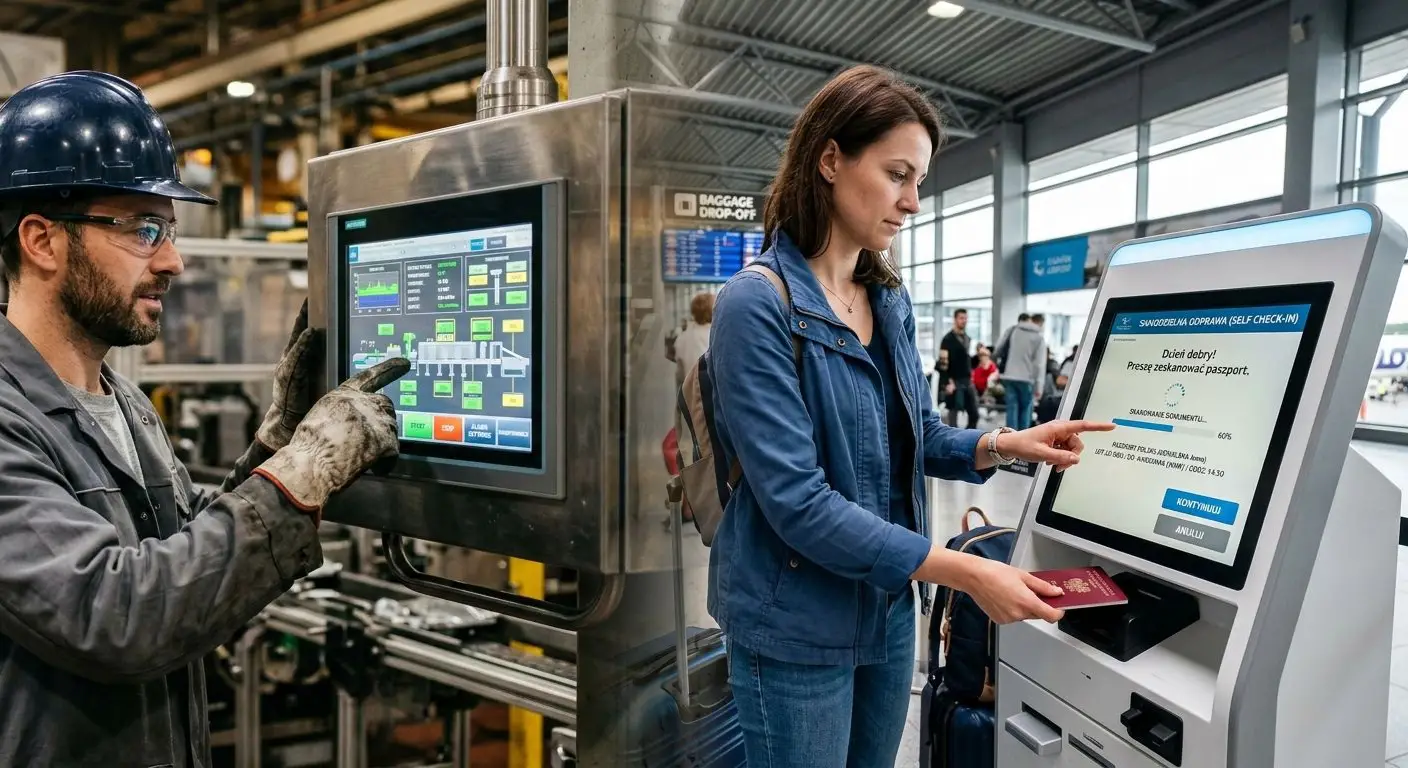
The touch interface has become one of the key elements of communication between the user and a device. The chosen touch technology largely determines the intuitiveness of operation, control precision, and overall user comfort – both in consumer electronics and in commercial and industrial solutions. In modern designs, selecting the right type of touch panel has a direct impact on functionality, durability, ergonomics, and the perceived quality of the entire device.
Unisystem
Talk to our team about display selection, technical fit, customization options and next steps for your application.
Knowledge Hub
More articles, guides and product insights from Unisystem.
Learn the essentials of LCD-TFT display control and enhance your display technology skills with practical tips.
Uncover the reasons behind the RAM shortage in 2026. Understand its impact on pricing and market outlook for the tech industry.
The touch interface has become one of the key elements of communication between the user and a device. The chosen touch technology largely determines the intuitiveness of operation, control precision, and overall user comfort – both in consumer electronics and in commercial and industrial solutions. In modern designs, selecting the right type of touch panel has a direct impact on functionality, durability, ergonomics, and the perceived quality of the entire device.
In this article, we compare the two most commonly used technologies: capacitive – CTP (Capacitive Touch Panel) and resistive – RTP (Resistive Touch Panel). Although both serve the same function as an input interface, they differ in their operating principles, performance characteristics, and optimal application areas.
In this article, we address the following questions, among others:
This is a comprehensive article designed for selective reading. You can start with the section of greatest interest – such as the operating principles of a specific technology, a direct comparison of CTP and RTP, or example application areas – and then explore other parts to build a broader context. A comparison table summarizing the key parameters of both technologies is also provided for convenience. Additionally, the article includes links to other materials on our blog that further expand on selected topics.
We hope this article serves as a practical knowledge resource to support designers in selecting the optimal touch technology at the device design stage. At the same time, we remain at your disposal – if you have any questions, require additional information, or would like to discuss a specific application, we encourage you to contact the Unisystem team.
A capacitive touchscreen is a solution that combines a display with a touch panel based on capacitive technology (CTP). It is responsible both for image presentation and for registering user interactions through touch detection.
The operating principle of CTP technology is based on measuring changes in the electrostatic field generated by a grid of transparent electrodes located beneath the glass surface. When the screen is touched with a finger or another conductive object, a local change in electrical capacitance occurs at the point of contact. This change is detected by the touch controller and translated into precise coordinates, enabling accurate identification of the touch position.
Thanks to high sensitivity, excellent positioning accuracy, and fast response times, capacitive touchscreens provide smooth and intuitive operation. For this reason, they have become the standard in modern user interfaces, where ergonomics, responsiveness, and design quality are key factors.
A capacitive touchscreen operates by measuring changes in electrical capacitance that occur on the surface of the touch panel when a user interacts with the screen. Its structure includes a layer of transparent electrodes that generate a constant electrostatic field. When the user touches the screen – for example with a finger – a local disturbance of this field occurs, resulting in a change in capacitance at a specific point.
The human finger, as a conductive object, draws a small amount of electrical charge from the screen surface. This change is then processed by the touch controller, which determines the precise coordinates of the contact point. The entire process takes place very quickly, ensuring high responsiveness and smooth user interaction.
An additional key feature of this technology is its ability to support multiple simultaneous touch points (multitouch). The panel can detect several independent changes in capacitance at the same time, enabling gestures such as zooming, rotating, or swiping with two or more fingers. This functionality significantly expands the design possibilities of user interfaces.
A capacitive touch panel (CTP) consists of several closely integrated layers, each performing a specific function in the touch detection process. Their precise construction directly affects the mechanical durability of the surface, touch sensitivity, and overall image quality.
The outermost part of a CTP panel is the protective glass layer, which serves both a mechanical and a functional role. It protects the screen against scratches, impacts, and other damage occurring during operation, while also acting as the direct interface for user interaction, influencing the overall user experience.
In CTP technology, the glass forms both the structural and aesthetic front of the device, offering a wide range of customization options. These include selecting the thickness to meet specific mechanical resistance classes (e.g. IK), adapting the shape and edge finishing (grinding, chamfering, rounding), printing – for example to highlight a manufacturer’s logo – as well as creating cut-outs for mechanical components.
Additional functional coatings can also be applied to the glass, such as anti-glare (AG), anti-reflective (AR), anti-fingerprint (AF), or anti-microbial (AM). These enhance image readability, improve resistance to contamination, and support surface hygiene, ultimately increasing user comfort.
Directly beneath the protective glass layer is a transparent grid of electrodes made of indium tin oxide (ITO – Indium Tin Oxide). This material combines good electrical conductivity with high light transmittance, enabling high display brightness. The ITO electrodes form a matrix of sensors arranged in a grid pattern, allowing precise detection of local changes in electrical capacitance at the touch point. The density and geometry of this grid directly influence detection resolution, system response time, and effective support for multitouch functionality.
The touch controller is a key electronic component of a CTP panel, responsible for reading and processing signals from the ITO electrode matrix. Its role is to continuously sample capacitance changes at individual grid nodes, filter out interference, and convert analog signals into digital data. Based on this information, the controller determines the exact coordinates of touch points using interpolation, drift compensation, and noise rejection algorithms.
The processed data is then transmitted to the control system (MCU) or directly to the application processor via standard communication interfaces such as I²C, SPI, or USB. Controller parameters – including sampling rate, processing resolution, computational performance, and the quality of detection algorithms – have a direct impact on panel response time, operational stability in environments with electromagnetic interference (EMI), and effective multitouch handling. In modern systems, this component largely determines the overall fluidity and precision of the user interface.
An important aspect of touch controller operation is the implementation of mechanisms that enhance resistance to electromagnetic interference. Modern controllers incorporate features such as noise rejection and frequency hopping.
The frequency hopping mechanism dynamically adjusts the sampling frequency when interference is detected within a specific range. This allows the system to avoid frequencies affected by interference while maintaining stable touch detection.
Noise rejection functions enable the system to filter out random or repetitive signals that do not correspond to actual touch events. Additionally, drift compensation and baseline tracking mechanisms are used to maintain stable performance under changing environmental conditions.
In practice, the sophistication of the controller’s algorithms directly affects the CTP panel’s resistance to electromagnetic interference, the stability of multitouch operation, and the reduction of phenomena such as ghost touch – false detection of touch points not initiated by the user, leading to unintended interface activations.

In practice, two main types of capacitive touchscreens (CTP) are distinguished, differing in structure, technical capabilities, and typical application areas. Although both are based on the same principle of detecting changes in electrical capacitance, their functionality and robustness vary significantly.
Surface capacitive technology is based on a uniform conductive layer applied to the surface of the glass. This solution features a relatively simple structure and limited touch detection resolution.
Compared to more advanced architectures, it offers lower positioning accuracy, lacks full multitouch support, and provides reduced resistance to mechanical damage and electromagnetic interference. As a result, it is currently used mainly in simple applications with limited functional requirements.
Projected capacitive (PCAP) is currently the most widely used and most advanced form of capacitive technology. It utilizes a matrix of transmitting and receiving electrodes located beneath the glass surface, forming a precise projection grid of the electrostatic field. This architecture enables accurate touch point localization, stable multitouch performance, and operation through thicker protective glass.
Thanks to its high mechanical durability, stable operation in environments with electromagnetic interference, and compatibility with various display types, PCAP technology is widely used in modern HMI interfaces.
A resistive touchscreen is a solution that combines a display with a touch panel based on resistive technology (RTP – Resistive Touch Panel). It is responsible for both image presentation and touch registration through the detection of pressure applied to the screen surface.
The operating principle of RTP technology is based on the use of two thin conductive layers separated by a microscopic spacer gap. When pressure is applied to the screen, the layers come into contact, causing a change in resistance at the contact point. The controller converts this change into X and Y coordinates, determining the exact location of the touch.
A resistive touchscreen operates by detecting physical pressure applied to its surface. The touch panel consists of two thin, transparent conductive layers separated by a microscopic spacer gap. In the idle state, these layers do not touch each other. When the screen is pressed, they make contact at a specific point, resulting in a local change in electrical resistance. The touch controller measures this change and determines the X and Y coordinates of the contact point.
An RTP screen does not require a conductive object – it responds to pressure alone. This means it can be operated with a finger, stylus, gloved hand, or various tools. This characteristic makes resistive technology well suited for environments with demanding operating conditions, where reliability and versatility of interaction are essential.
The structure of a resistive touch panel is based on a simple yet proven layer configuration, where the interaction between individual layers enables precise touch detection based on mechanical pressure.
The top flexible layer forms the outer, active surface of the RTP panel and is responsible for registering user-applied pressure. It is made of a flexible material, typically a plastic substrate coated with a thin conductive layer. When pressure is applied, this layer deforms, allowing contact with the lower layer and enabling touch detection.
Its flexibility allows operation with a finger, stylus, tools, or while wearing gloves. However, it also makes the surface more susceptible to scratches and gradual mechanical wear during operation.
The bottom layer is the inner, rigid structural element of the RTP panel and is coated with a conductive material. It serves as a stable base for the entire structure and as a reference point for measuring resistance changes occurring upon pressure.
Due to its rigidity, it ensures accuracy and repeatability in touch detection, which is particularly important in applications involving intensive and long-term use.
The air gap acts as a spacer layer separating the top flexible layer from the bottom conductive layer. In the idle state, it maintains a small distance between the two surfaces, preventing unintended contact and false activations.
When pressure is applied, the top layer deforms and comes into contact with the bottom layer within this gap, enabling touch detection. The parameters of the air gap – such as its height and the type of spacers used – directly affect panel sensitivity, the force required for activation, and the overall mechanical durability of the structure.
The touch controller is the electronic component responsible for interpreting signals from the resistive panel. When pressure is applied to the screen surface, a contact point is created between the top and bottom layers, resulting in a local change in electrical resistance.
The controller precisely measures this change and converts it into a digital signal. Based on the acquired values, it calculates the X and Y coordinates of the touch point, taking into account panel calibration, material characteristics, and any variations resulting from operation.
The controller is also responsible for noise filtering, signal stability, and communication with the device’s main system (e.g. via interfaces such as SPI, I²C, or USB, depending on the system architecture). This ensures reliable, repeatable, and fast transmission of touch data, directly contributing to proper user interface performance.

In practice, two main types of RTP screens are most commonly used, differing in electrical architecture, durability, and intended application areas.
4-wire technology is the simplest form of resistive touchscreen. In this solution, both conductive layers participate in coordinate measurement – alternately determining the X and Y axes.
Its simple structure and lower production cost make it suitable for applications with moderate usage intensity and for cost-sensitive devices. However, it should be noted that the top flexible layer also serves as a measurement element, so its gradual wear over time may affect accuracy and long-term stability.
5-wire technology features a more advanced measurement architecture. In this design, the elements responsible for determining coordinates are primarily located in the bottom rigid layer, while the top layer mainly serves a conductive and contact function.
This approach improves operational stability, as wear of the flexible layer has a limited impact on measurement accuracy. For this reason, 5-wire panels are more commonly used in industrial devices, where the touchscreen is subject to intensive and long-term use.
CTP and RTP technologies serve the same purpose – enabling device control via touch – but differ in operating principles, structure, and performance characteristics. Understanding these differences is essential when selecting the right solution for a specific application and operating environment. Below is a comparison of selected aspects of both technologies.
The key difference between CTP and RTP lies in the touch detection mechanism. Capacitive screens respond to changes in the electrostatic field caused by contact with a conductive object, typically the user’s finger. Detection occurs without the need to apply pressure to the screen surface.
In contrast, resistive screens (RTP) operate based on physical pressure, which causes two conductive layers to come into contact and results in a change in electrical parameters at the contact point. In practice, this means that CTP enables light, effortless interaction, while RTP requires applied force to register input.
RTP technology responds to physical pressure, allowing it to be operated with virtually any object – a finger, stylus, pen tip, or other tools with a small contact area. It does not require electrical conductivity, which provides high flexibility in interaction. This approach is often used in systems where precise point selection is more important than gesture support.
CTP technology operates based on changes in the electrostatic field and therefore typically requires a conductive input, most commonly a finger or a dedicated stylus. It supports multitouch gestures and advanced user interfaces. In practice, CTP is better suited for modern HMI systems where smooth and intuitive interaction is essential.
Resistive screens can be operated without issues while wearing gloves – including latex, nitrile, rubber, or textile – because they respond to physical pressure rather than electrical properties. This ensures full functionality regardless of the type of hand protection used.
Capacitive screens require contact with a conductive object, which means glove operation may be limited. To ensure proper functionality with gloves made of materials such as latex or nitrile – commonly used in medical, laboratory, pharmaceutical, or food processing environments – proper controller tuning and sensitivity calibration are required. Modern PCAP solutions offer dedicated glove modes, but these must be correctly configured at the device design stage.

Capacitive screens (CTP) offer high touch detection accuracy and smooth response even to a light touch. The absence of required pressure translates into high user comfort, a natural interaction experience, and reduced fatigue during prolonged use. This technology is particularly well suited for applications that require fast, precise, and repeatable interactions.
Resistive screens (RTP) provide good pointing accuracy but require physical pressure to register input. This can affect user comfort during intensive operation, especially in environments where interaction is frequent and dynamic. The interaction feel is more “mechanical,” which noticeably differs from the smooth experience characteristic of capacitive technology.
One of the key advantages of CTP technology is multitouch support – the ability to detect multiple contact points simultaneously. This enables the implementation of advanced gestures (e.g. zooming, rotating, multi-point swiping) and the design of more complex and intuitive user interfaces. In practice, this results in improved ergonomics and easier integration with modern HMI systems.
Standard RTP screens typically detect only a single touch point at a time. This limits support for multitouch gestures and reduces functionality in applications requiring parallel user interaction. It is worth noting, however, that industrial variants of resistive panels offering multitouch emulation are available. These solutions are more complex, more expensive, and generally less precise compared to capacitive technology.
In integrated modules, where the display is combined with a touch panel, image quality is influenced by factors such as the number of optical layers, their light transmittance, and the method of integrating individual components.
A key aspect is light transmission, which affects the effective brightness of the display and is particularly important in backlit technologies such as LCD-TFT. In such designs, the image is formed as light from the backlight passes through successive optical layers – including the liquid crystal matrix, filters, polarizers, and the touch panel. Each additional layer in the optical path reduces the amount of light reaching the user, directly impacting final brightness and readability. In emissive technologies (e.g. OLED), this relationship differs, but in industrial applications LCD-TFT solutions still dominate, making brightness a critical parameter.
CTP technology ensures high image quality thanks to the use of glass and thin, transparent conductive layers. This structure minimizes optical distortion and enables higher light transmittance, resulting in better contrast and improved readability.
RTP technology is based on a multi-layer structure with an air gap, which increases the number of optical interfaces and may lead to reduced light transmission and degraded image parameters, such as contrast.
To minimize optical losses in LCD-TFT modules, optical bonding is increasingly used. This process involves filling the space between the display and the touch panel with a transparent optical adhesive, eliminating the air gap between components. This solution is most commonly applied in CTP panels, although it can also be used in selected RTP designs.
Considering these factors, when integrating a touch panel with an LCD-TFT display, it is essential to carefully manage luminance parameters – particularly by selecting a display with sufficiently high nominal brightness, adjusted to the operating conditions and accounting for brightness losses resulting from touch panel integration.
CTP technology performs very well in applications that must ensure reliable operation under intensive use – for example, devices deployed in public spaces and used by thousands of users daily. The protective glass layer offers high resistance to abrasion, allowing the panel to maintain stable performance and surface aesthetics even with frequent interaction.
RTP technology, due to its flexible top layer, may gradually wear out, become scratched, or deform over prolonged use. Although it is less prone to shattering, its durability under intensive operating conditions is generally lower compared to CTP panels.

RTP technology, due to its operating principle based on pressure detection, exhibits low susceptibility to electromagnetic interference. It does not rely on measuring changes in the electrostatic field, which allows it to maintain stable operation even in environments with elevated EMI levels.
CTP technology operates based on detecting changes in the electrostatic field, making it more sensitive to electromagnetic interference compared to resistive solutions. However, stable operation in industrial environments does not depend solely on shielding and grounding, but also on the capabilities of the touch controller.
Modern CTP controllers implement mechanisms such as noise rejection, frequency hopping, and multi-stage signal filtering. Dynamic adjustment of the sampling frequency helps reduce the impact of interference generated by power converters, motors, or supply lines. At the same time, noise rejection and compensation algorithms enable the system to distinguish between actual touch input and electromagnetic interference.
As a result, a properly designed CTP system – including appropriate shielding, grounding, power line filtering, and a controller with advanced detection algorithms – can meet electromagnetic compatibility (EMC) requirements and operate reliably even in demanding industrial environments.
The presence of liquids, lubricants, oils, or gels on the screen surface can significantly affect touch panel performance, with the extent depending on the underlying technology.
RTP technology operates based on physical pressure between conductive layers, so the presence of water, lubricants, or oils on the surface typically does not cause unintended activations. However, contamination may reduce user comfort and accelerate wear of the top layer.
CTP technology relies on detecting changes in the electrostatic field, which means that the presence of conductive substances can interfere with its operation. This may lead to reduced sensitivity, incorrect signal interpretation, or – in extreme cases – the occurrence of “ghost touch,” i.e. unintended activations. In industrial solutions, this risk is mitigated through proper front sealing, controller sensitivity tuning, signal filtering, and appropriate shielding.
CTP panels use a glass surface, typically tempered, which provides high resistance to scratches and abrasion. This allows the panel to maintain its appearance and clarity even under intensive use. However, it should be noted that glass is a brittle material and may crack under strong impact.
RTP panels use a flexible top layer, which is more resistant to impacts and point pressure. At the same time, it is more susceptible to scratches and wear, which over time can affect transparency and touch accuracy, especially in frequently used areas.
Therefore, the choice of technology should take into account the type of mechanical stress expected in a given application.
The table below summarizes the key differences between CTP and RTP technologies:
| Feature / Parameter | CTP (Capacitive Touch Panel) | RTP (Resistive Touch Panel) |
| Operating principle | Response to changes in the electrostatic field caused by contact with a conductive object | Response to physical pressure causing contact between conductive layers |
| Method of interaction | Finger / capacitive stylus; gloves in glove mode; non-conductive objects – not supported by default | Finger, stylus, gloves, any object with an appropriate contact tip |
| Required pressure | No – a light touch is sufficient | Yes – pressure is required |
| Operation with latex or nitrile gloves | Yes, provided proper touch controller calibration | Yes |
| Operation with textile gloves | No | Yes |
| Precision | Higher, stable across the entire active area | Lower, dependent on calibration and pressure uniformity |
| Multitouch support | Yes | No (typically single-touch only) |
| Light transmittance | Higher | Lower |
| Impact on image quality | Lower impact on optical parameters – higher light transmittance, better contrast and clarity | Greater impact on optical parameters – lower light transmittance, possible reduction in contrast and clarity |
| Resistance to wear | Higher | Lower |
| Scratch resistance | Higher | Lower |
| Resistance to point impacts | Lower | Higher |
| Production cost | Higher | Lower |
The comparison of technical parameters above helps identify areas where each technology performs best. In many applications, both capacitive and resistive panels can be used; however, the final choice is typically determined by the operating environment, method of interaction, and expectations regarding the user interface.
Capacitive panels are used in, among others:
Resistive screens are used in, among others:
The choice between CTP and RTP technology should be driven by the actual operating conditions of the device and its intended method of use. The following list of questions helps structure key decision criteria already at the design stage.

We encourage you to contact the Unisystem team directly – by going through these questions together, we can help you select the technology best suited even for the most demanding applications.
The fundamental difference between CTP and RTP lies in the method of touch detection. CTP responds to changes in the electrostatic field caused by a conductive object, while RTP detects physical pressure that brings conductive layers into contact.
This difference stems directly from the distinct construction of the two panel types and translates into their usability characteristics – including user comfort, pointing accuracy, multitouch capability, mechanical resistance, and surface durability. As a result, each technology is best suited to different types of applications.
In most applications, CTP technology – especially in the PCAP variant – offers higher precision. RTP provides the best accuracy when used with a stylus, but it requires pressure, which affects interaction comfort and smoothness.
Standard CTP screens respond to conductive objects, so in their default configuration they may not work with certain types of gloves. To ensure proper operation with gloves, appropriate touch controller calibration is required.
It should be noted that performance depends on the material and thickness of the gloves. Capacitive screens typically work well with latex, nitrile, and rubber gloves. Issues may occur with gloves made exclusively from textile materials, which do not conduct electrical charge.
No, standard RTP screens detect only a single touch point at a time. The lack of multitouch support is one of the main limitations of this technology compared to CTP.
Yes. In capacitive panels, protective glass is a standard structural component.
The glass protects the sensor layer from scratches, impacts, and environmental factors, increasing the panel’s mechanical resistance and durability. It also enables the application of additional coatings, such as anti-glare (AG), anti-reflective (AR), or oleophobic (anti-fingerprint – AF), which improve image readability and user comfort.
In addition, protective glass offers a wide range of customization options. Its thickness can be selected to meet specific mechanical resistance requirements (e.g. to comply with a defined IK rating). It can also be shaped into specific geometries, printed (providing an ideal surface for branding, such as a manufacturer’s logo), and mechanically processed – for example, by adding cut-outs for mechanical buttons.
It depends. In simple, less demanding applications, a resistive panel can operate without additional protective glass. However, in applications involving intensive use or where there is a risk of accidental or intentional damage, the use of protective glass with appropriately selected thickness is recommended. This solution increases front panel durability and reduces the risk of premature wear of the touch layer.
It depends.
RTP technology is inherently better suited for demanding environments – mainly due to its pressure-based touch detection. As a result, it performs well in the presence of moisture, contamination, glove operation, or tool-based interaction. However, this operating principle also limits multitouch capabilities and reduces interface design flexibility.
CTP technology can also meet demanding environmental requirements, but it requires proper system design – including appropriate panel calibration, controller configuration, and selection of protective glass. With proper integration, high environmental resistance can be achieved while maintaining aesthetics, smooth operation, and greater interface capabilities.
Yes, CTP screens can be used in outdoor applications, but they require proper design of the entire module. Key aspects include selecting appropriate protective glass, ensuring proper sealing (IP rating), and achieving the required mechanical resistance (IK rating).
In outdoor use, proper panel calibration and controller configuration are also essential – including sensitivity adjustment, signal filtering, and mitigation of the effects of contamination on the screen surface. A properly designed CTP system can operate reliably and stably in outdoor conditions.
Yes, despite the rapid development of capacitive technology, RTP is still widely used in industrial devices. In many applications, reliability, versatility of interaction (e.g. operation with tools), and cost optimization are key factors, making resistive technology a fully justified solution.
Do you have questions about selecting the right touch technology? Contact us – we will help you choose the solution best suited to your application.

End of Life, or EOL – a term that can raise concerns in the world of electronics. Especially when it applies to key components of your product.
Read more →